TCP/IP Guide
I. OSI Model
The OSI reference model is, after all, just a “model.” It only provides a series of rough definitions for the roles of each layer, and does not define protocols and interfaces in detail. It can only serve as guidance for learning about and designing protocols. Therefore, if you want to understand the details of a protocol, you still need to refer to the specific specification of that protocol itself.
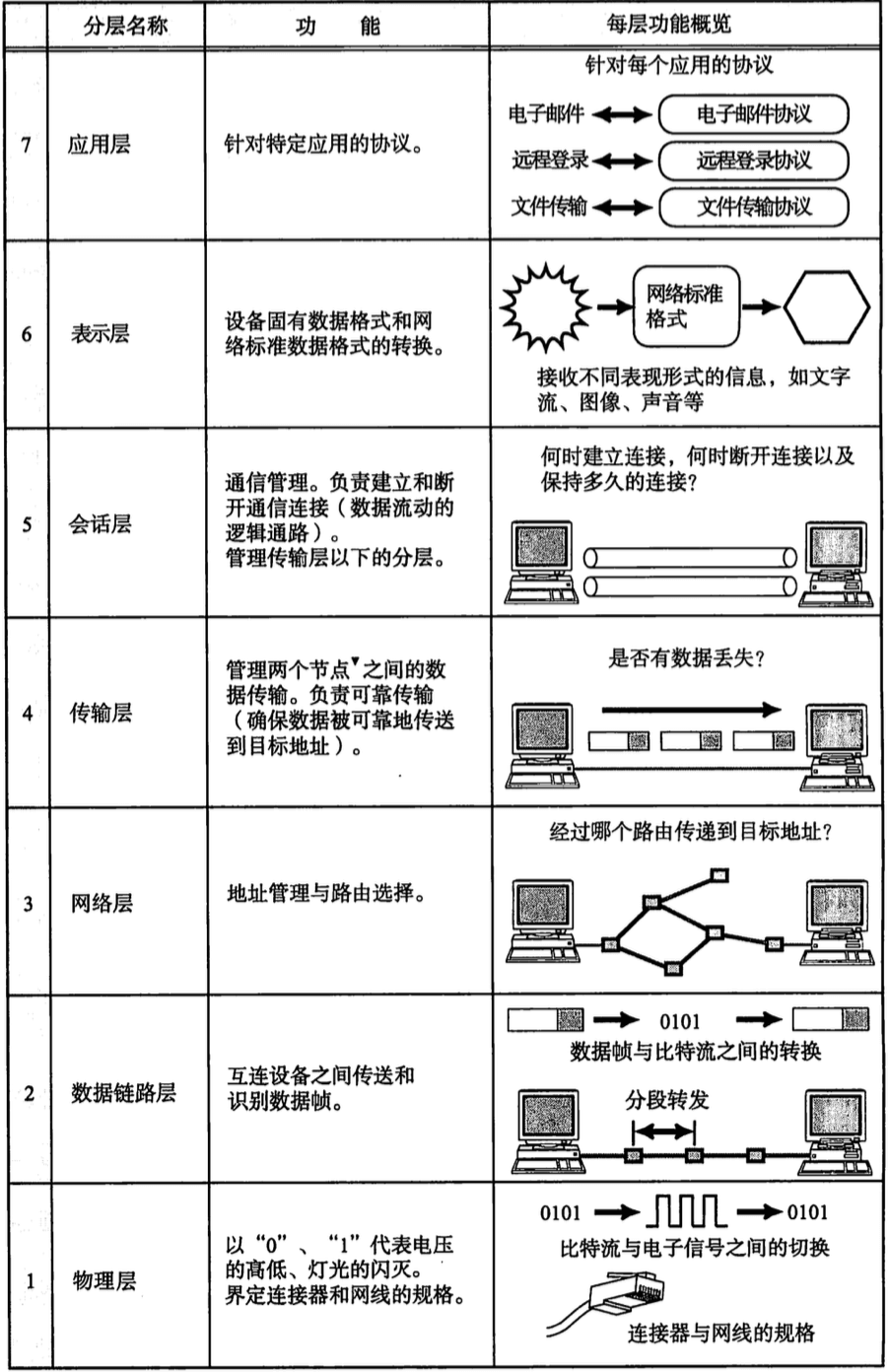
The figure above is the definition of the seven-layer model from the book Illustrated TCP/IP.
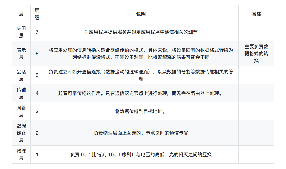
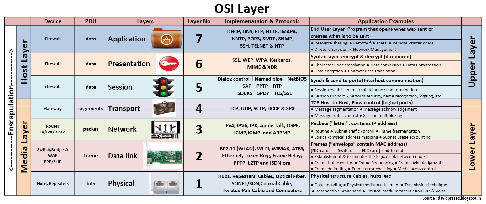
The figure above shows where some protocols sit in the OSI model. It is worth noting that DNS is an application-layer protocol, while SSL spans the fifth layer, the session layer, and the sixth layer, the presentation layer. TLS is located at the fifth layer, the session layer. (Protocols such as DNS, SSL, and TLS will be analyzed and explained in detail later.)
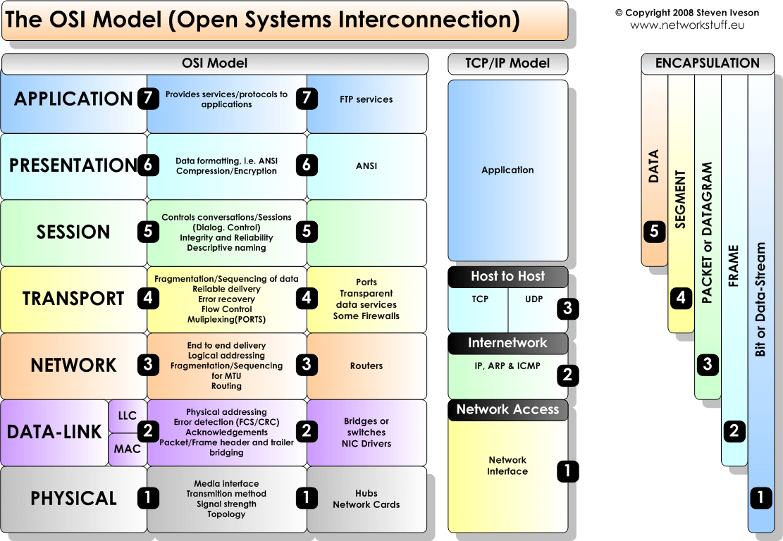
The figure above compares the TCP/IP model and the OSI model.
Next are two diagrams from the Internet. I disagree with some of the content in these diagrams. As for what is right and wrong in the following two diagrams, feel free to open an issue to discuss.
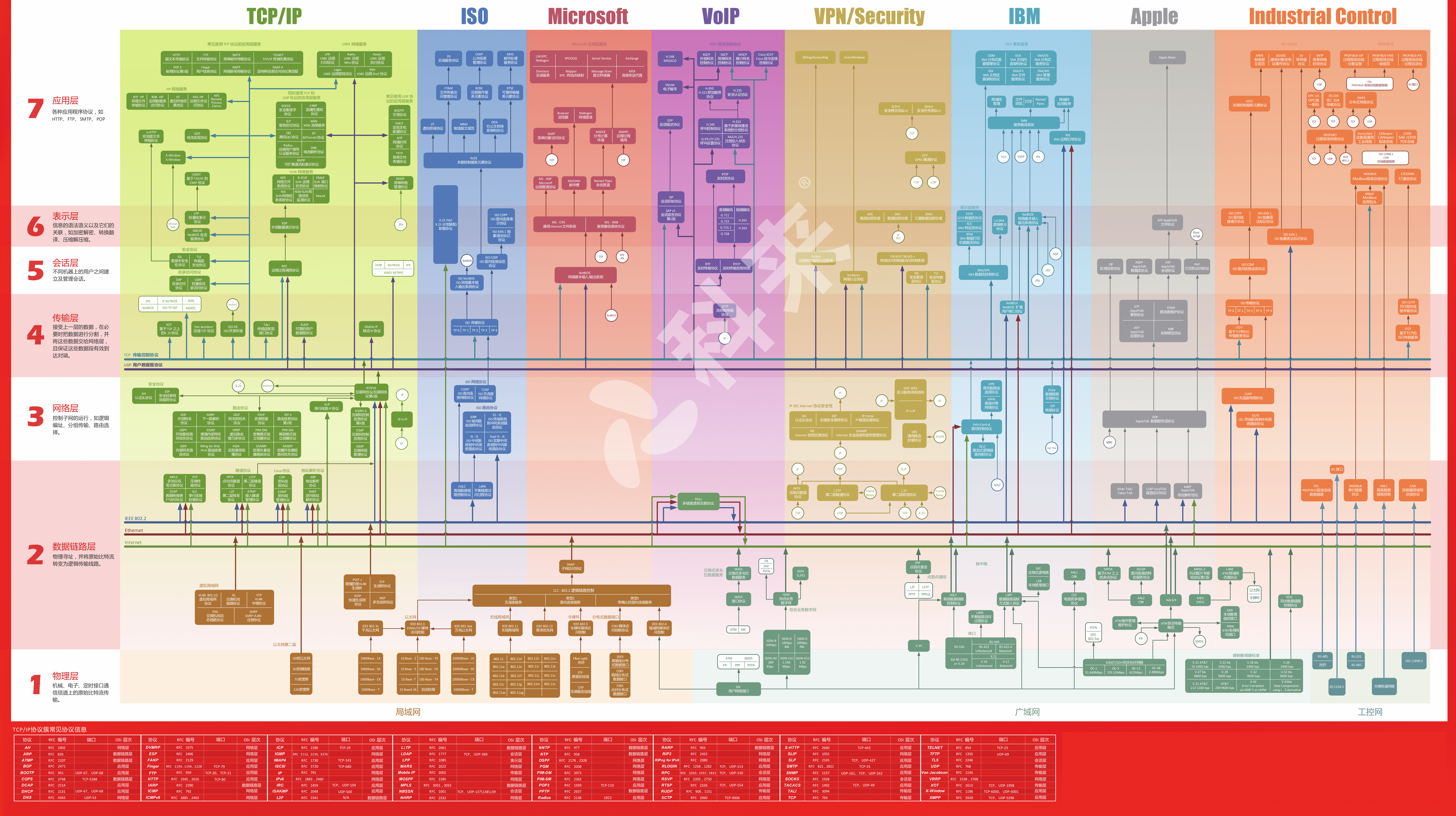
The diagram above says DNS is a network-layer protocol, but many friends around me unanimously consider it an application-layer protocol. Another mistake is that SSL is shown as spanning the sixth and seventh layers; this is still incorrect.
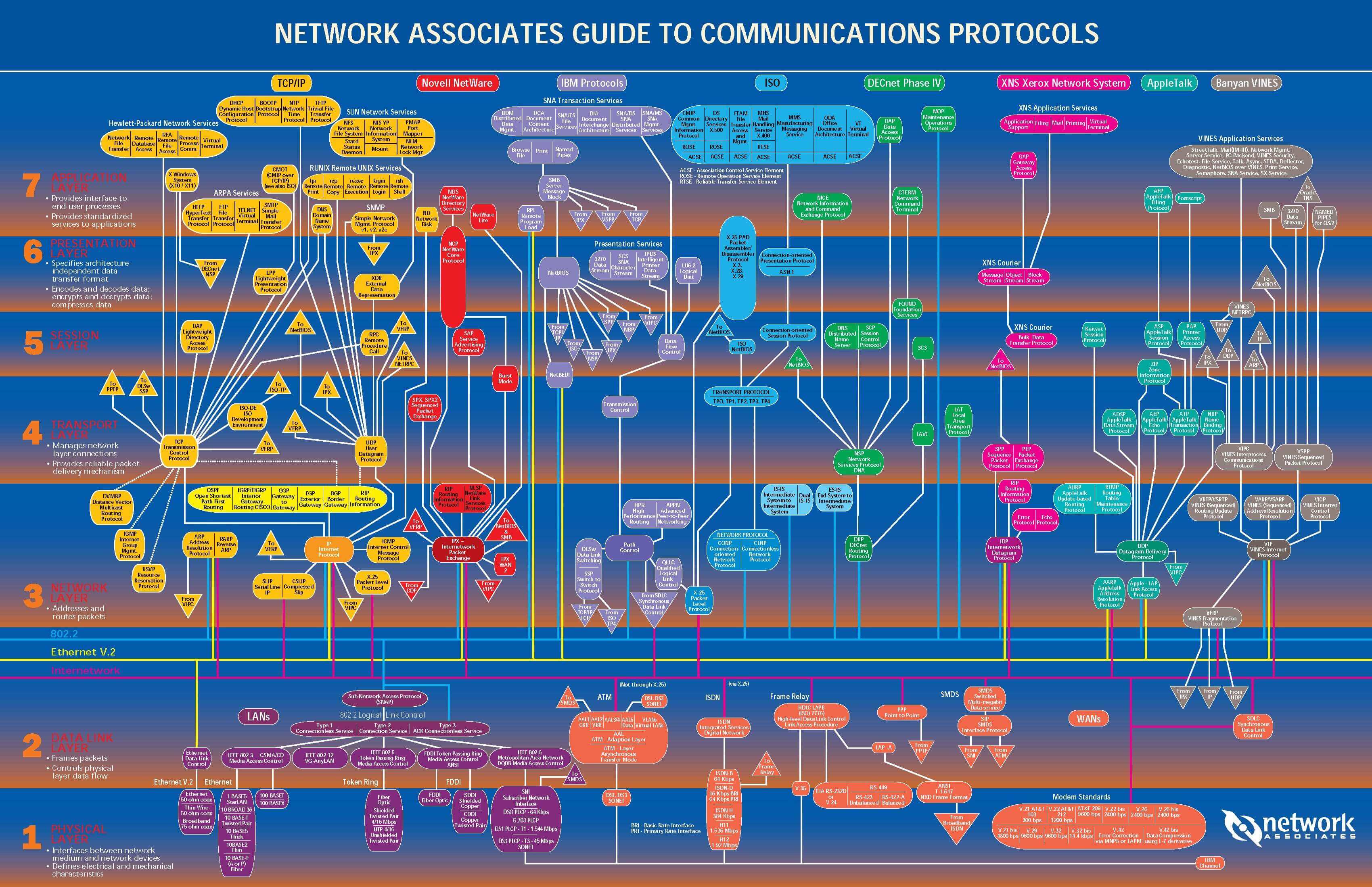
In the diagram above, DNS is placed at the application layer, which I agree with, and it also shows that DNS is based on UDP and TCP. This is also very good! (For those who do not know why DNS is also based on TCP, this will be analyzed in detail in the DNS section.) However, the diagram above does not show which layer SSL/TLS belongs to.
I believe that although the two diagrams above look very complex and detailed, if you examine them carefully, both still have omissions and inaccuracies.
II. Example of Communication in the OSI Reference Model
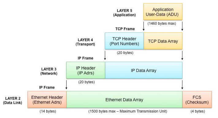
The figure above shows the data flow during communication in the five-layer TCP/IP model. One point worth mentioning: in an Ethernet frame at the data link layer, excluding the 14-byte Ethernet header and the 4-byte FCS trailer, the payload length in the middle is between 46 and 1500 bytes.
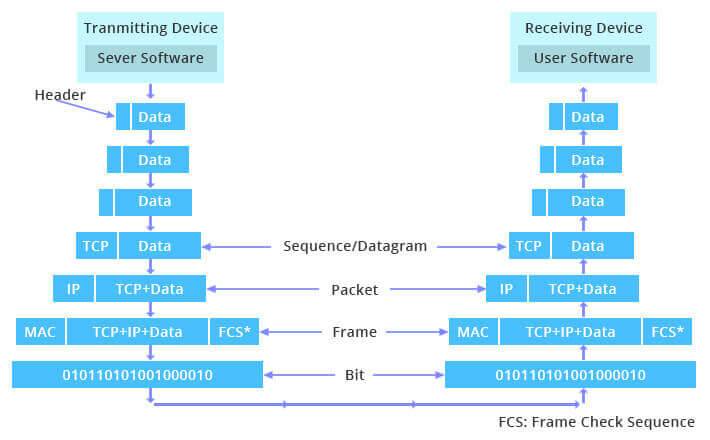
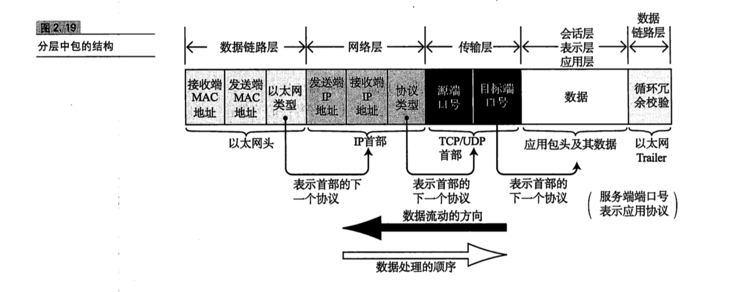
The figure above shows the data flow during communication in the seven-layer OSI model. In the seven-layer model shown above, the physical layer transmits a byte stream; the unit of a packet at the data link layer is called a frame. The unit of packets at the IP, TCP, and UDP network layer is called a datagram. Information in TCP and UDP data streams is called a segment. Finally, the unit of data in application-layer protocols is called a message.
From the seventh application layer downward layer by layer, protocol headers are continuously wrapped around the data. These protocol headers are effectively the “face” of the protocol.
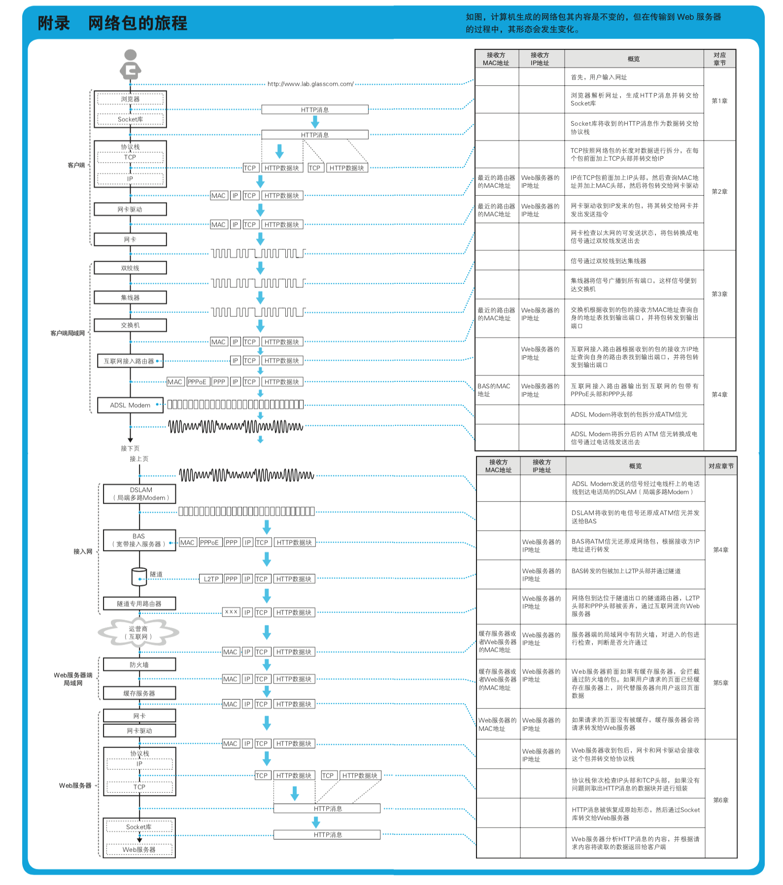
The figure above is from the appendix of the book How Networks Really Work.
From the three diagrams above, we can clearly see how data flows when one application communicates with another application or with a server.
III. TCP/IP Standardization Process
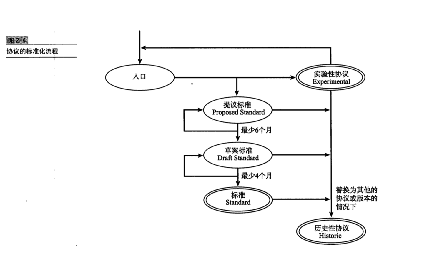
The standardization process for TCP/IP protocols is roughly divided into the following stages: first, the Internet-Draft stage; second, if the work is considered suitable for standardization, it is recorded as an RFC and enters the Proposed Standard stage; third, the Draft Standard stage; and finally, it becomes a true Standard.
IV. Ethernet Frame Structure
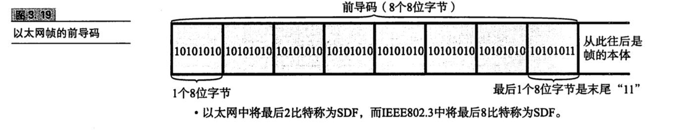
Before an Ethernet frame, there is a Preamble section, which is used as a marker to allow the peer network adapter to ensure synchronization with it. At the end of the preamble there is a field called the SFD (Start Frame Delimiter). The SFD in Ethernet is the final 2 bits, 11, while the SFD in IEEE802.3 is the final 8 bits, 10101011.
The structures of Ethernet frames and IEEE802.3 frames also differ, as shown below.
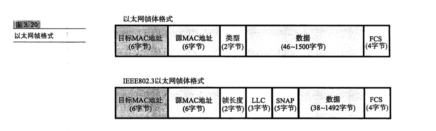
At the end of each frame is a 4-byte FCS (Frame Check Sequence). FCS stands for Frame Check Sequence and is used to determine whether a frame was damaged during transmission (for example, by electronic noise interference). The FCS stores the remainder obtained by dividing the transmitted frame by a certain polynomial. The received frame is calculated in the same way; if the resulting value matches the FCS, it indicates that no error occurred.
Ethernet frames are relatively common, so let’s discuss the Ethernet frame structure in detail. In addition to the destination MAC address and source MAC address, there is also a type code.
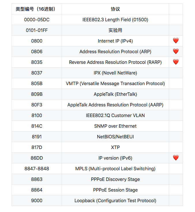
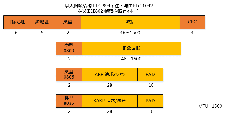
Now let’s look at the IEEE802.3 frame structure. Compared with Ethernet frames, IEEE802.3 frames contain several additional parts: frame length, LLC, and SNAP.
The data link layer can be subdivided into two layers: the Media Access Control (MAC) layer and the Logical Link Control (LLC) layer. The media access control layer performs control based on header information specific to different data links, such as Ethernet or FDDI. The logical link control layer performs control based on frame header information common to different data links, such as Ethernet or FDDI.
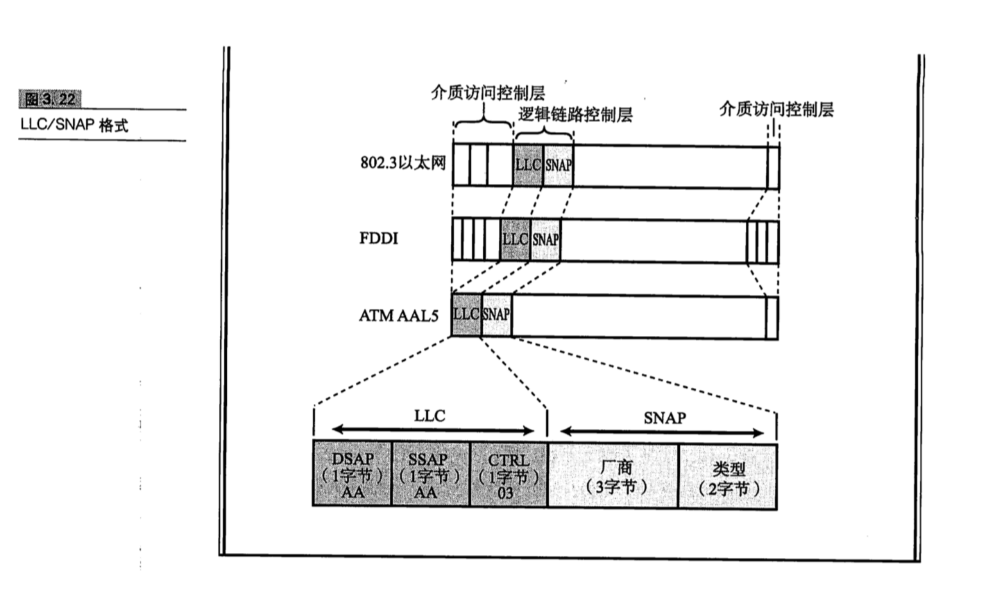
SNAP is 5 bytes in total. Excluding the first 3 bytes, which represent the vendor, the remaining 2 bytes have the same meaning as the type field in an Ethernet frame.
In VLAN switches, an additional 4 bytes are appended to the frame structure, making it look like this:
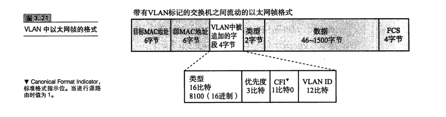
V. IP Protocol
The network layer mainly consists of IP (Internet Protocol) and ICMP (Internet Control Message Protocol).
IP is connectionless for two reasons: first, simplicity; second, speed. Its goal is to deliver packets to the final destination address on a best-effort basis. Simple and fast. Reliability is left to TCP.
Different data links have different Maximum Transmission Units (MTUs).
An Ethernet frame can carry at most 1500 bytes, FDDI can carry up to 4352 bytes, and ATM can carry up to 9180 bytes.
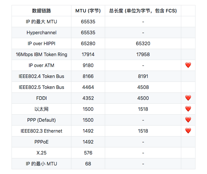
Because MTUs differ, IP fragmentation and reassembly are required. Routers only perform fragmentation; the endpoint (the destination host) performs reassembly.
During fragmentation by a router, if any fragment is lost, the entire IP datagram becomes invalid. To address this problem, a technique called Path MTU Discovery was introduced.
The host first obtains the minimum MTU among all data links along the entire path, and fragments data according to that size. Therefore, no router along the transmission path needs to perform fragmentation.
To find the path MTU, the host first sends the entire packet and sets the Don’t Fragment flag in the IP header to 1. In this way, when a router encounters a packet that would require fragmentation to process, it does not fragment it; instead, it drops the packet directly and sends an unreachable message back to the host via ICMP.
The host sets the MTU in the ICMP notification as the current MTU, and fragments the data according to that MTU. This repeats until no further ICMP notifications are received; the MTU at that point is the path MTU.
Taking data transmission over UDP as an example:
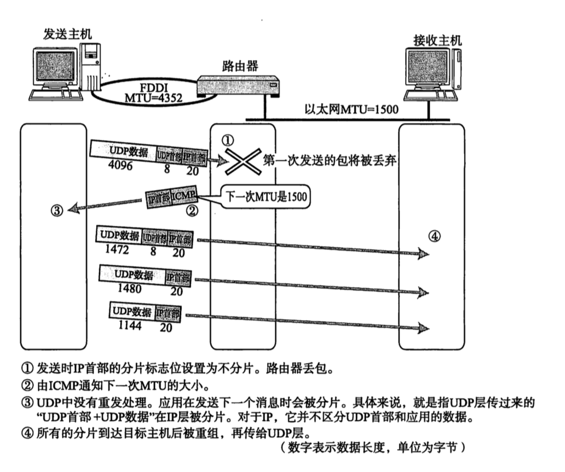
VI. IPv4 Header
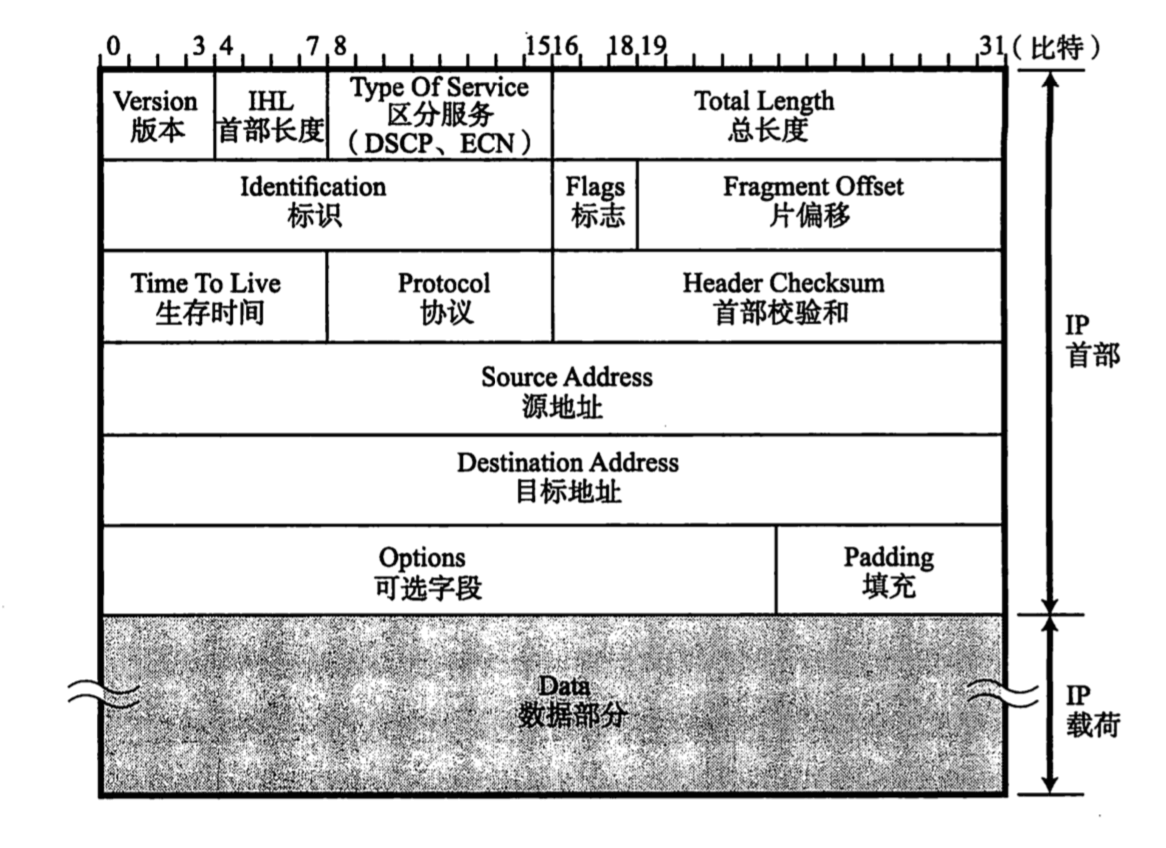
Several fields in the middle are described as follows:
- Version:
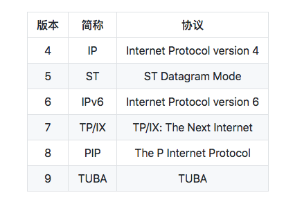
The version number in the IPv4 header is 4.
Header Length (IHL: Internet Header Length):
This consists of 4 bits and indicates the size of the IP header, in units of 4 bytes (32 bits). For an IP packet without options, the header length is set to “5”. In other words, when there are no options, the IP header length is 20 bytes (4 * 5 = 20).Differentiated Services:
This consists of 8 bits and is used to indicate quality of service. However, current networks generally ignore this field. Some have proposed subdividing the TOS field itself into two fields: DSCP (Differential Services Codepoint) and ECN (Explicit Congestion Notification).Total Length:
This is 16 bytes long and represents the total number of bytes of the IP header plus the data portion. Because this field is 16 bytes long, the maximum length of an IP packet is 65535 (2^16^) bytes.Identification:
The identification ID is used to identify fragments. Different fragments have different identification values. Even if the IDs are the same, if the destination address, source address, or protocol differs, they are still treated as different fragments.Flags:
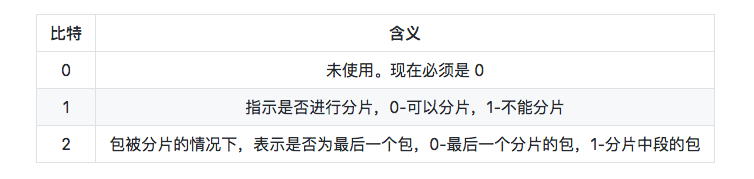
Fragment Offset:
This consists of 13 bits and can represent up to 8192 (2^13^) relative positions. Because the flags occupy three bits, the unit is 8 bytes. It can represent positions in the original data up to 8 * 8192 = 65536 bytes.Time To Live (TTL):
This consists of 8 bits. Its original meaning was to record, in seconds, how long the current packet should live on the network. In practice, however, it refers to how many routers the packet has traversed. Each time it passes through a router, TTL is decremented by 1; when it reaches 0, the packet is discarded.Protocol:
This consists of 8 bits and indicates which protocol the next header after the IP header belongs to.Header Checksum:
This consists of 16 bits (2 bytes). This field checks only the header of the datagram, not the data portion. It is mainly used to ensure that the IP datagram has not been corrupted.Source Address:
This consists of 32 bits (4 bytes).Destination Address:
This consists of 32 bits (4 bytes).Options:
The length is variable, and this is usually used only for experiments or diagnostics. It includes the following information: security level, source route, route record, and timestamp.Padding:
Also called filler. When options are present, the header length may not be an integer multiple of 32 bits. Therefore, the field is padded with 0s to align it to an integer multiple of 32 bits.
VII. IPv6 Header
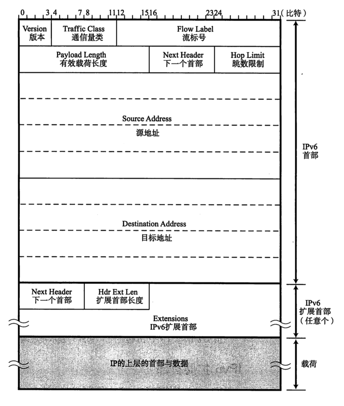
- Version:
The version number in the IPv6 header is 6.
Traffic Class:
This corresponds to the TOS (Type Of Service, TOS) field in IPv4 and also consists of 8 bits. Originally, this field was intended to be removed in IPv6 (because it had no practical effect in IPv4), but it was ultimately retained.Flow Label:
Consists of 20 bits and is used for Quality of Service (QoS) control.Payload Length:
Refers to the data portion of the packet. This differs from IPv4: in IPv4, TL (Total Length) represents the total length. Here, however, Payload Length does not include the header.Next Header:
Equivalent to the Protocol field in IPv4, consisting of 8 bits. It usually indicates that the upper-layer protocol above IP is TCP or UDP. However, when IPv6 extension headers are present, this field indicates the protocol type of the first extension header that follows.Hop Limit:
Consists of 8 bits and has the same meaning as TTL in IPv4. It is decremented by 1 each time the packet passes through a router. When it reaches 0, the packet is discarded.Source Address:
Consists of 128 bits (eight 16-bit bytes). Indicates the sender’s IP address.Destination Address:
Consists of 128 bits (eight 16-bit bytes). Indicates the receiver’s IP address.
8. DNS (Domain Name System)
DNS can automatically convert that string into a specific IP address. DNS applies not only to IPv4, but also to IPv6.
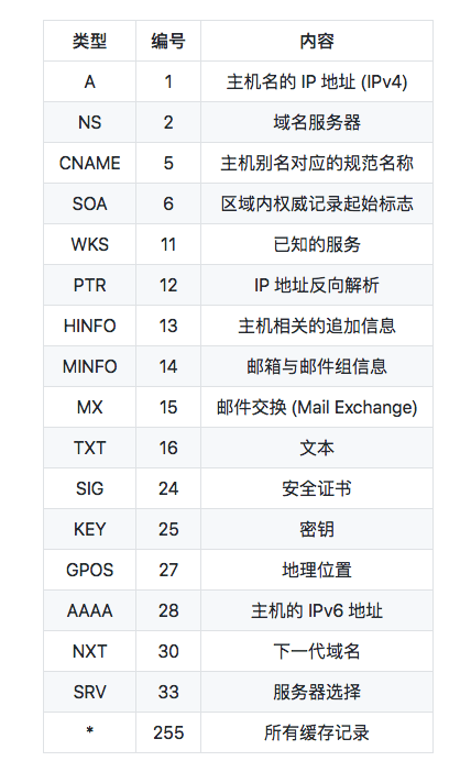
There is a basic DNS message format [RFC6195]. It is used for all DNS operations: queries, responses, zone transfers, notifications, and dynamic updates.
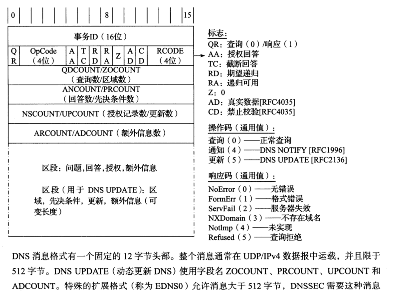
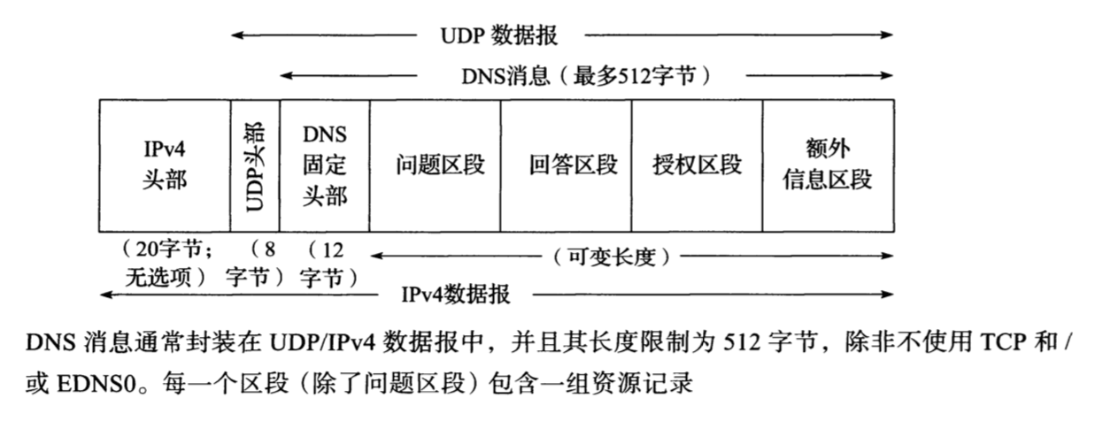
For both TCP and UDP, the well-known port number for DNS is 53. The most common format uses the UDP/IPv4 datagram structure shown below.
When a resolver sends a query message and the TC bit is set in the returned response message (“truncated”), the real response message is longer than 512 bytes, so the server returns only the first 512 bytes. The resolver may issue the request again using TCP; this is now a configuration that must be supported [RFC5966]. This allows messages larger than 512 bytes to be returned, because TCP splits larger messages into multiple segments.
Therefore, DNS is based on both UDP and TCP.
When a secondary name server for a zone starts up, it typically performs a zone transfer from the primary name server for that zone. A zone transfer may be triggered by a timer or by a DNSNOTIFY message. Full zone transfers use TCP because they can be large. Incremental zone transfers, in which only updated entries are transferred, may use UDP first, but if the response message is too large, they switch to TCP, just like regular queries.
When UDP is used, both resolver and server application software must implement their own timeouts and retransmissions. Recommendations for this are given in [RFC1536]. It recommends an initial timeout of at least 4 seconds, with subsequent timeouts causing the timeout interval to grow exponentially. Linux and UNIX-like systems allow retransmission timeout parameters to be changed by modifying the /etc/resoIv.conf file (by setting the timeout and attempts parameters).
9. ARP (Address Resolution Protocol)
ARP is a protocol for resolving address-related problems. Using the destination IP address as a clue, it locates the MAC address of the network device that should receive the next data packet. ARP can only be used with IPv4, not IPv6. In IPv6, ICMPv6 can replace ARP by sending Neighbor Discovery messages.
10. ICMP
The main functions of ICMP include confirming whether an IP packet was successfully delivered to the destination address, reporting the specific reason why an IP packet was discarded during transmission, and improving network configuration. With these capabilities, you can determine whether the network is operating normally, whether the configuration is incorrect, and whether a device has any abnormalities, making network troubleshooting easier. ICMP messages can be roughly divided into two categories: error messages that report the cause of an error, and query messages used for diagnostics.
In IPv6, the role of ICMP is expanded. Without ICMPv6, IPv6 cannot communicate normally.
11. TCP
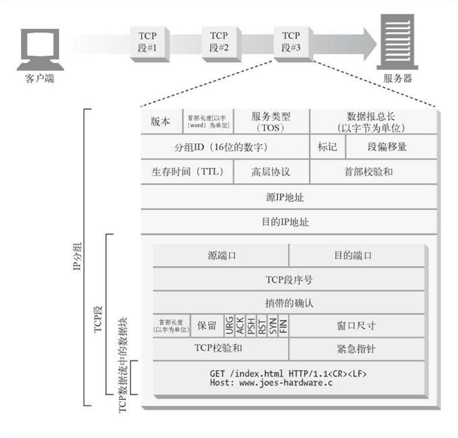
- TCP provides a connection-oriented, reliable byte-stream service.
- In a TCP connection, only two parties communicate with each other. Broadcast and multicast cannot be used with TCP.
- TCP uses checksums, acknowledgments, and retransmission mechanisms to ensure reliable transmission.
- TCP orders data segments and uses cumulative acknowledgments to ensure that data remains in order and is not duplicated.
- TCP uses a sliding window mechanism to implement flow control, and performs congestion control by dynamically changing the window size.
TCP achieves reliable transmission through mechanisms such as checksums, sequence numbers, acknowledgments, retransmission control, connection management, and window control.
The two key elements in the IP protocol are the source IP address and the destination IP address. The main role of the transport layer is to enable communication between applications. Therefore, transport-layer protocols add three elements: the source port number, the destination port number, and the protocol number. With these five pieces of information, a communication can be uniquely identified.
Different ports are used to distinguish different applications on the same host. Suppose you open two browsers: requests sent by browser A will not be received by browser B, because A and B have different ports.
The protocol number is used to distinguish whether TCP or UDP is being used. Therefore, communication between the same two processes on the same two hosts can still be correctly distinguished when TCP and UDP are used respectively.
To summarize in one sentence: as long as any one of the five pieces of information—“source IP address, destination IP address, source port number, destination port number, and protocol number”—is different, the communication is considered different.
TCP header: excluding the options field, the TCP header length is 20 byte
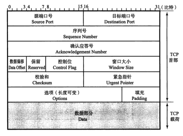
TCP has no separate fields for packet length and data length. The TCP packet length can be obtained from the IP layer, and the data length can be derived from the TCP packet length.
Sequence Number:
This field is 32 bits long. The sequence number indicates the position of the data being sent. Each time data is sent, it is increased by the number of bytes in that data. The sequence number does not start from 0 or 1; instead, when the connection is established, a random number generated by the computer is used as the initial value and passed to the receiving host through the SYN packet.Acknowledgement Number:
The acknowledgement number field is 32 bits long. It indicates the sequence number of the data that should be received next. In practice, it means that all data up to the acknowledgement number minus one has been received. After the sender receives this acknowledgement, it can assume that all data before this sequence number has been received correctly. It is valid when ACK=1.Data Offset: This field indicates from which bit in the TCP packet the data portion transmitted by TCP should be counted; it can also be viewed as the length of the TCP header. This field is 4 bits long, with a unit of 4 bytes (that is, 32 bits). If the options field is not included, the data offset field can be set to 5. Conversely, if the value of this field is 5, it means that everything from the very beginning of the TCP packet through 20 bytes is the TCP header, and the remaining portion is TCP data.
Reserved:
This field is mainly reserved for future extension. It is 4 bits long and is generally set to 0. Even if a received packet has a nonzero value in this field, the packet will not be discarded.Control Flag:
This field is 8 bits long. From left to right, it is shown in the following figure:

CWR (Congestion Window Reduced):
The CWR flag and the following ECE flag are both used for the ECN field in the IP header. When the ECE field is 1, it notifies the peer that the congestion window has been reduced.
ECE (ECN-Echo):
The ECE flag indicates ECN-Echo. When set to 1, it tells the peer that there is congestion on the network path from the peer to this side.
URD (Urgent Flag):
When this bit is 1, it means the packet contains data that must be processed urgently.
ACK (Acknowledgement Flag):
When this bit is 1, it means the acknowledgement field becomes valid.
PSH (Push Flag):
When this bit is 1, it indicates that the received data should be immediately passed to the upper-layer application protocol. A value of 0 means it does not need to be passed up immediately and can be buffered first.
RST (Reset Flag):
When this bit is 1, it indicates that an abnormal condition has occurred in the TCP connection and the connection must be forcibly terminated.
SYN (Synchronize Flag):
When this bit is 1, it indicates a desire to establish a connection and sets the random initial value of the sequence number in the sequence number field.
FIN (Fin Flag):
When this bit is 1, it indicates that no more data will be sent in the future and the connection should be closed.
- Checksum:
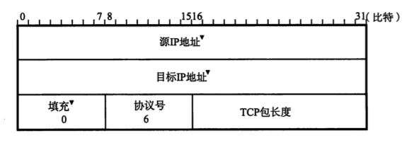
TCP’s checksum is similar to UDP’s. The difference is that TCP’s checksum cannot be disabled (UDP can disable checksumming by filling the checksum field with 0). As with UDP datagrams, TCP segments also include a 12-byte pseudo-header when computing the checksum.
Note: the pseudo-header of a TCP segment serves a dual-checking purpose: 1. Through the IP address check in the pseudo-header, TCP can confirm that IP has not accepted a datagram that was not addressed to this host; 2. Through the protocol field check in the pseudo-header, TCP can confirm that IP has not delivered to TCP a datagram that should have been passed to another higher-layer protocol (such as UDP, ICMP, or IGMP).
Urgent Pointer:
This field is 16 bits long and is valid only when the URG control bit is 1. The value of this field indicates the pointer to the urgent data in this segment.Options:
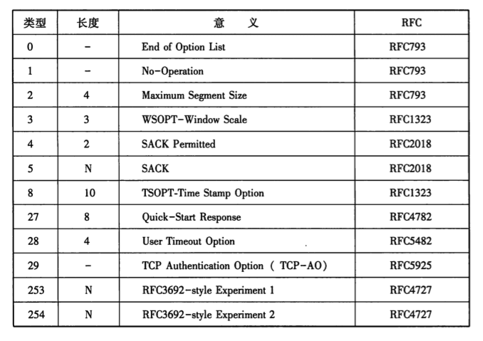
The options field is used to improve TCP transmission performance. Because it is controlled based on the data offset (header length), its maximum length is 40 bytes. In addition, the options field should be adjusted as much as possible to an integer multiple of 32 bits. Representative options are shown below:
TCP Sliding Window
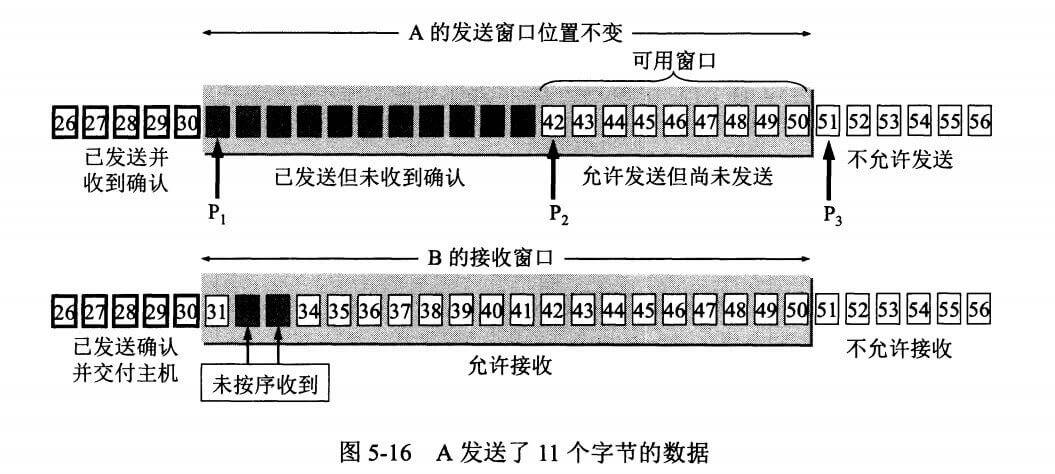
A window is part of the buffer and is used to temporarily store a byte stream. The sender and receiver each have a window. The receiver tells the sender its window size through the window field in the TCP segment, and the sender sets its own window size based on this value and other information.
Bytes within the send window are allowed to be sent, and bytes within the receive window are allowed to be received. If the bytes on the left side of the send window have already been sent and acknowledged, the send window slides to the right by a certain distance until the first byte on the left is no longer in the sent-and-acknowledged state. The receive window slides similarly: if the bytes on the left side of the receive window have already been acknowledged and delivered to the host, the receive window slides to the right.
The receive window only acknowledges the last byte that has arrived in order within the window. For example, if the bytes already received by the receive window are {31, 32, 34, 35}, then {31, 32} arrived in order, while {34, 35} did not. Therefore, only byte 32 is acknowledged. After the sender receives an acknowledgement for a byte, it knows that all bytes before that byte have been received.
TCP Reliable Transmission
TCP uses timeout-based retransmission to achieve reliable transmission: if an already-sent segment is not acknowledged within the timeout interval, that segment is retransmitted.
The time elapsed from sending a segment to receiving its acknowledgement is called the round-trip time RTT. The weighted average round-trip time RTTs is calculated as follows:
The timeout interval RTO should be slightly greater than RTTs. The timeout interval used by TCP is calculated as follows:
where RTTd is the deviation.
TCP Flow Control
Flow control is used to control the sender’s transmission rate and ensure that the receiver has enough time to receive the data.
The window field in the acknowledgment segment sent by the receiver can be used to control the sender’s window size, thereby affecting the sender’s transmission rate. If the window field is set to 0, the sender cannot send data.
TCP Congestion Control
If the network becomes congested, packets will be lost. At that point, the sender will continue retransmitting, which further increases network congestion. Therefore, when congestion occurs, the sender’s rate should be controlled. This is similar to flow control, but the motivation is different. Flow control ensures that the receiver has enough time to receive the data, whereas congestion control reduces the level of congestion across the entire network.
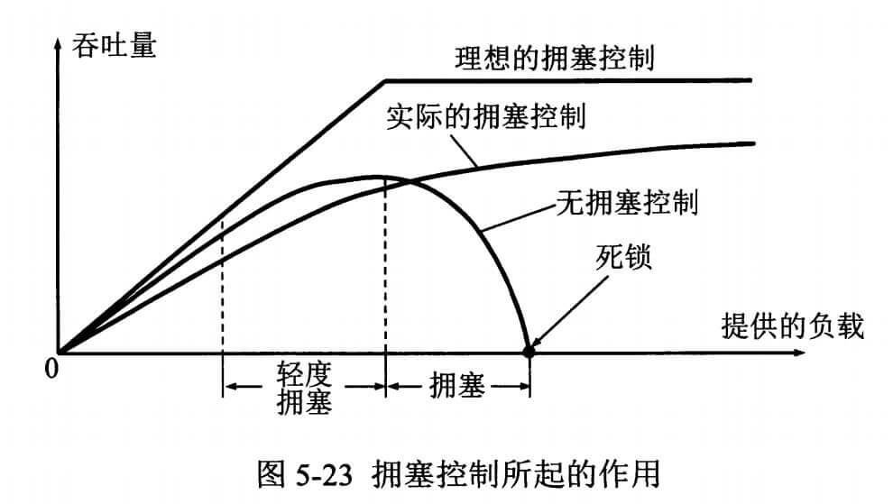
TCP mainly performs congestion control through four algorithms: slow start, congestion avoidance, fast retransmit, and fast recovery. The sender needs to maintain a state variable called the congestion window (cwnd). Note the difference between the congestion window and the sender window: the congestion window is only a state variable; what actually determines how much data the sender can send is the sender window.
For ease of discussion, make the following assumptions:
- The receiver has a sufficiently large receive buffer, so flow control does not occur;
- Although TCP windows are byte-based, here the window size is measured in segments.
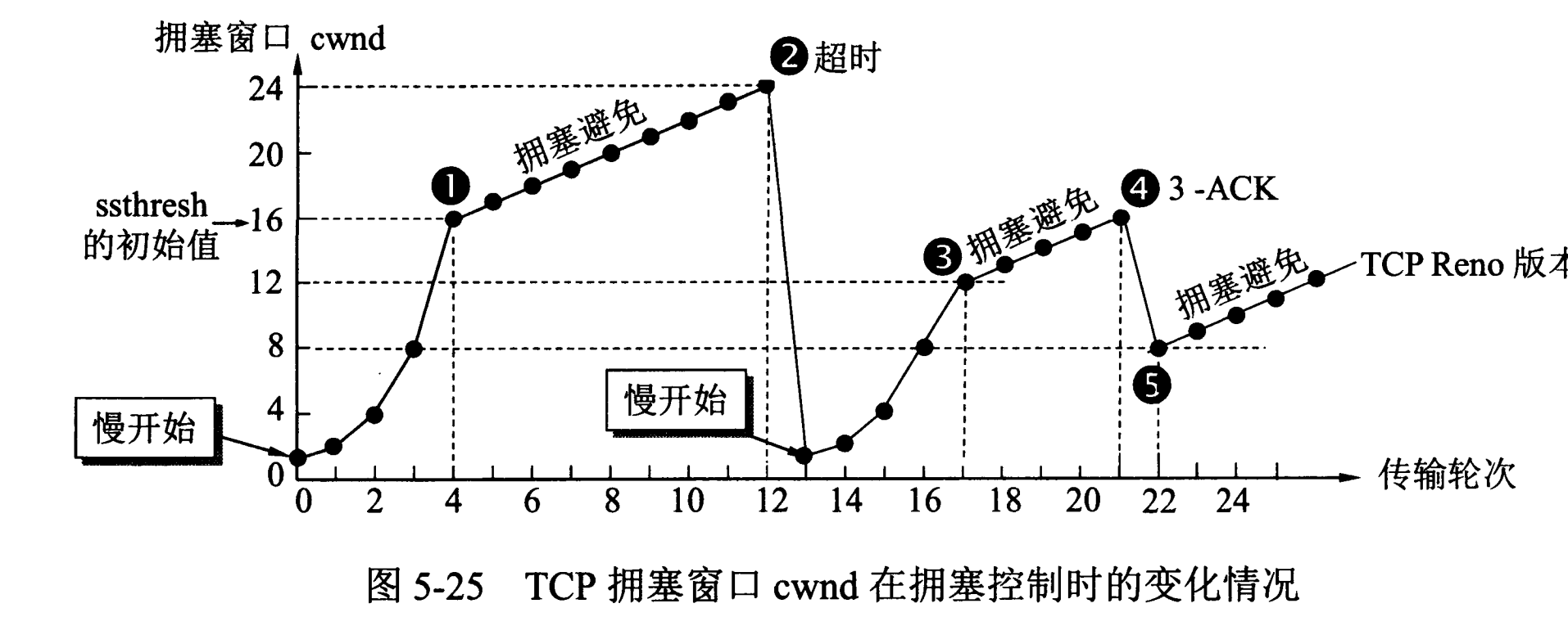
1. Slow Start and Congestion Avoidance
Transmission initially uses slow start: set cwnd=1, so the sender can send only 1 segment. After receiving an acknowledgment, cwnd is doubled, so the number of segments the sender can subsequently send is: 2, 4, 8 …
Notice that slow start doubles cwnd every round, which makes cwnd grow very quickly. As a result, the sender’s transmission rate increases too fast, making network congestion more likely. A slow-start threshold ssthresh is set; when cwnd >= ssthresh, congestion avoidance begins, and cwnd increases by only 1 per round.
If a timeout occurs, set ssthresh = cwnd/2, and then run slow start again.
2. Fast Retransmit and Fast Recovery
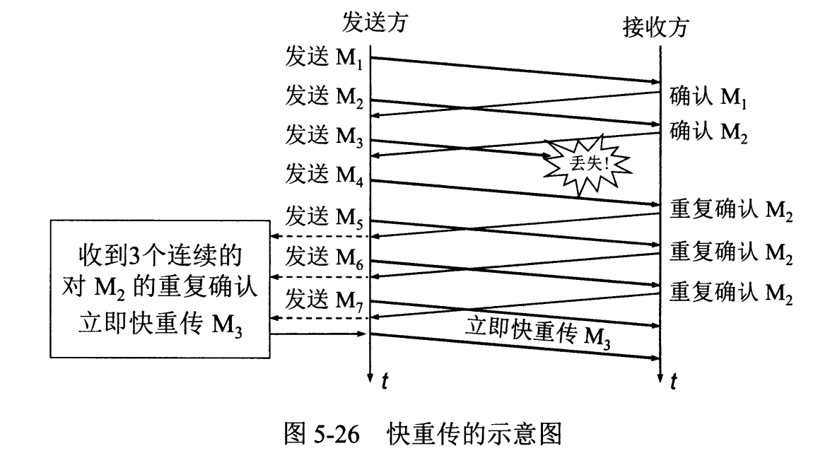
On the receiver side, every received segment should trigger an acknowledgment for the ordered segments already received. For example, if M1 and M2 have already been received, and M4 is then received, an acknowledgment for M2 should be sent.
On the sender side, if three duplicate acknowledgments are received, it can determine that the next segment has been lost. For example, if three acknowledgments for M2 are received, then M3 has been lost. At this point, fast retransmit is performed, and the next segment is retransmitted immediately.
In this case, only individual segments have been lost, rather than the network being congested. Therefore, fast recovery is performed: set ssthresh = cwnd/2 and cwnd = ssthresh. Note that this directly enters congestion avoidance.
Twelve. UDP
UDP stands for User Datagram Protocol. UDP does not provide complex control mechanisms. It uses IP to provide connectionless communication services. Even if packet loss occurs during transmission, UDP is not responsible for retransmission; even if packets arrive out of order, UDP has no correction mechanism. UDP is connectionless, so it can send data at any time.
It is mainly used in the following scenarios:
- Communication with a small total number of packets (DNS, SNMP, etc.)
- Multimedia communication such as video and audio (instant messaging)
- Application communication limited to specific networks such as LANs
- Broadcast communication (broadcast, multicast)
UDP header:
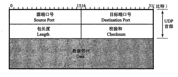
Packet length:
This field stores the sum of the UDP header length and the data length.Checksum:
The checksum is used to determine whether data was corrupted during transmission. When calculating this checksum, not only the source port number and destination port number are considered, but also the source IP address, destination IP address, and protocol number in the IP header (these are also known as the UDP pseudo-header). This is because all five of these elements are required to identify a communication session. If the checksum considered only the port numbers, then corruption in the other three elements would be invisible to the application. This could cause an application that should not receive the packet to receive it, while the application that should receive the packet does not.
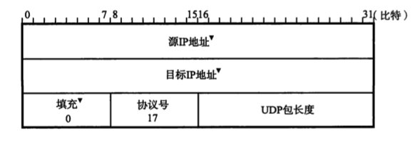
UDP uses the pseudo-header shown above to compute the checksum.
UDP is a simple protocol. Its formal specification, [RFC0768], is only 3 pages long (including references). The services it provides to user processes (above the IP layer) are port numbers and checksums. It has no flow control, no congestion control, and no error correction. It does provide error detection (optional for UDP/IPv4, but mandatory for UDP/IPv6) and preserves message boundaries.
UDP is most commonly used when the overhead of establishing a connection should be avoided, when multi-endpoint delivery is needed (multicast, broadcast), or when TCP’s relatively “heavyweight” reliability semantics (such as ordering, flow control, and retransmission) are not required. Thanks to multimedia and peer-to-peer applications, UDP is seeing increasing use, and it is also the primary protocol supporting VoIP [RFC3550][RFC3261]. It is also the traditional method for encapsulated traffic that must traverse NAT without introducing too much additional overhead (only 8 bytes for the UDP header). UDP is used in support of an IPv6 transition mechanism (Teredo) and in the STUN method that helps NAT traversal. UDP is also used for IPsec NAT traversal. Another use is supporting DNS.
Thirteen. TCP vs. UDP
TCP provides reliable communication transport, while UDP is often used for communication transport where broadcasting and fine-grained control are left to the application.
TCP is used when the transport layer needs to implement reliable transmission. Because it is connection-oriented and includes mechanisms such as ordering control and retransmission control, it can provide reliable transmission for applications.
UDP is mainly used for communication or broadcast communication that requires high-speed transmission and real-time behavior. Broadcast-based protocols such as RIP and DHCP also rely on UDP.
Note: TCP cannot guarantee that data will definitely be received by the peer, because that is impossible. What TCP can do is deliver the data to the receiver if possible; otherwise, it notifies the user (by giving up retransmission and terminating the connection). Therefore, strictly speaking, TCP is not a 100% reliable protocol either. What it provides is reliable delivery of data or reliable notification of failure.
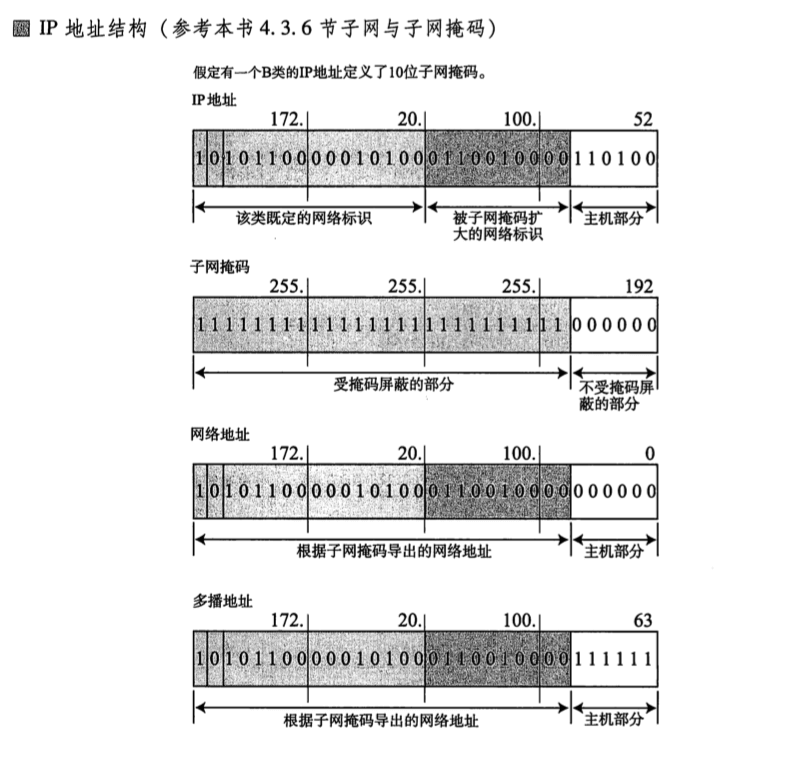
Fourteen. IP Address Structure
IPv4 address structure:
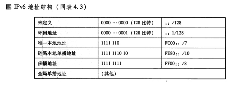
IPv6 address structure:
Fifteen. TCP Three-Way Handshake
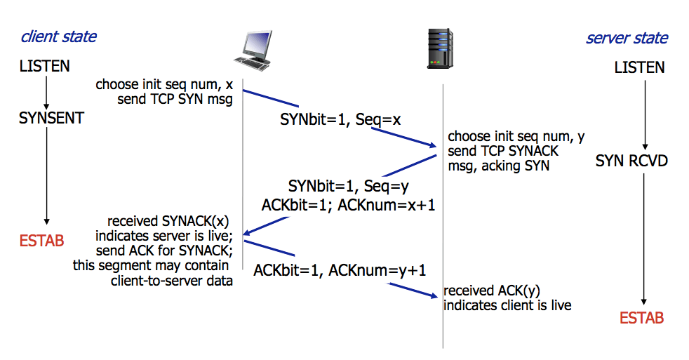
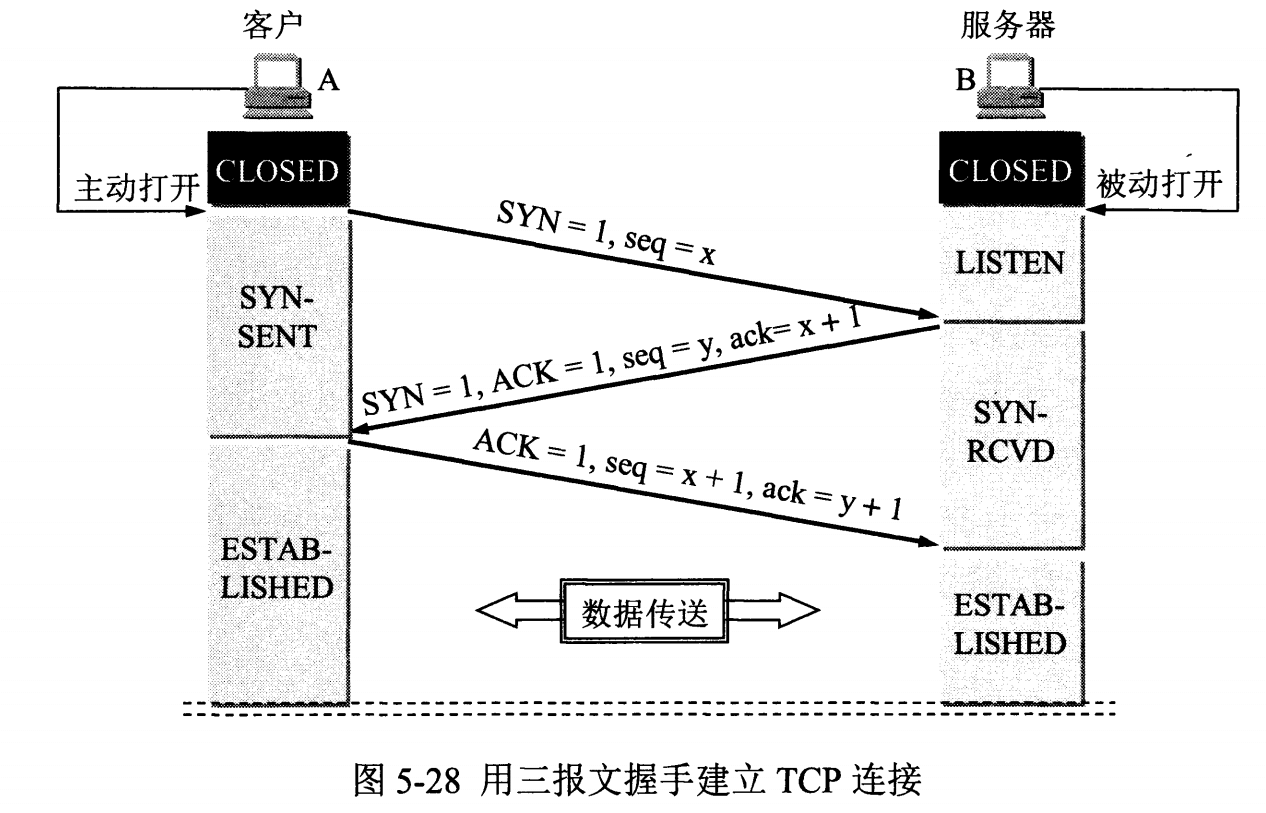
Establishing a TCP connection between a client and a server requires sending a total of 3 packets. This process is called the three-way handshake. As described above, the segment sequence number, acknowledgment number, and sliding window size are all established during this process. In socket programming, when the client executes connect(), the three-way handshake is triggered.
The so-called three-way handshake refers to the fact that establishing a TCP connection requires the client and server to send a total of 3 packets.
The purpose of the three-way handshake is to connect to the specified port on the server, establish a TCP connection, synchronize the sequence numbers and acknowledgment numbers of both endpoints, and exchange TCP window size information. In socket programming, when the client executes connect(), the three-way handshake is triggered.
- First handshake (SYN=1, seq=x):
The client sends a TCP packet with the SYN flag set to 1, indicating the server port the client intends to connect to, as well as the initial sequence number X, which is stored in the Sequence Number field of the packet header. The implementation of sequence numbers currently changes over time, so the sequence number is different every time a connection is established
After sending it, the client enters the SYN_SEND state.
- Second handshake (SYN=1, ACK=1, seq=y, ACKnum=x+1):
The server sends back an acknowledgment packet (ACK) in response. That is, both the SYN flag and the ACK flag are set to 1. The server chooses its own ISN sequence number and places it in the Seq field. At the same time, it sets the Acknowledgement Number to the client’s ISN plus 1, namely X+1. After sending it, the server enters the SYN_RCVD state.
- Third handshake (ACK=1, ACKnum=y+1)
The client sends another acknowledgment packet (ACK). The SYN flag is 0 and the ACK flag is 1. It adds 1 to the sequence number field in the ACK sent by the server, places it in the acknowledgment field, and sends it to the peer; it also writes its own ISN+1 into the data segment.
After sending it, the client enters the ESTABLISHED state. When the server receives this packet, it also enters the ESTABLISHED state, and the TCP handshake is complete.
The following diagrams illustrate the three-way handshake process:
Why Three Handshakes
Following ordinary intuition, we might think that two handshakes are enough, and the third acknowledgment seems redundant. So why does the TCP protocol go to the trouble of adding this extra handshake?
This is because, in network requests, we should always remember: “the network is unreliable, and packets can be lost.” Suppose there is no third acknowledgment. The client sends a SYN to the server, requesting that a connection be established. Due to latency, the server does not receive this packet in time. The client then sends another SYN packet. Recall the sequence number mentioned when introducing the TCP header: these two packets obviously have the same sequence number.
Suppose the server receives the second SYN packet, establishes communication, and after some time the communication ends and the connection is closed. At this point, the originally sent SYN packet has just arrived at the server, and the server sends another ACK acknowledgment. Since a connection is established after only two handshakes, the server will now establish a new connection. However, the client does not believe it requested a connection, so it will not send data to the server. This causes the server to establish an empty connection, wasting resources for nothing.
With the three-way handshake, the server does not establish the connection until it receives the client’s response. Therefore, in the scenario above, the client will receive an identical ACK packet, at which point it will discard the packet and will not perform the third handshake with the server. This prevents the server from establishing an empty connection.
SYN Attack:
1. What Is a SYN Attack (SYN Flood)?
During the three-way handshake, the TCP connection after the server sends SYN-ACK and before it receives the client’s ACK is called a half-open connection. At this point, the server is in the SYN_RCVD state. After receiving the ACK, the server can transition to the ESTABLISHED state.
A SYN attack means that, within a short period of time, the attacking client forges a large number of nonexistent IP addresses and continuously sends SYN packets to the server. The server replies with acknowledgment packets and waits for client acknowledgment. Because the source addresses do not exist, the server must keep retransmitting until timeout. These forged SYN packets occupy the pending connection queue for a long time, causing normal SYN requests to be dropped. As a result, the target system runs slowly; in severe cases, it can cause network congestion or even system paralysis.
A SYN attack is a typical DoS/DDoS attack.
2. How to Detect a SYN Attack?
Detecting a SYN attack is very straightforward. When you see a large number of half-open states on the server, especially when the source IP addresses are random, you can basically conclude that it is a SYN attack. On Linux/Unix, you can use the built-in netstats command to detect SYN attacks.
# netstat -na TCP | grep SYN_RECV | more,
3. How Do You Defend Against SYN Attacks?
SYN attacks cannot be completely prevented unless the TCP protocol is redesigned. What we do is mitigate the damage caused by SYN attacks as much as possible. Common methods for defending against SYN attacks include:
- Shortening the timeout (SYN Timeout)
- Increasing the maximum number of half-open connections
- Filtering gateway protection
- SYN cookies
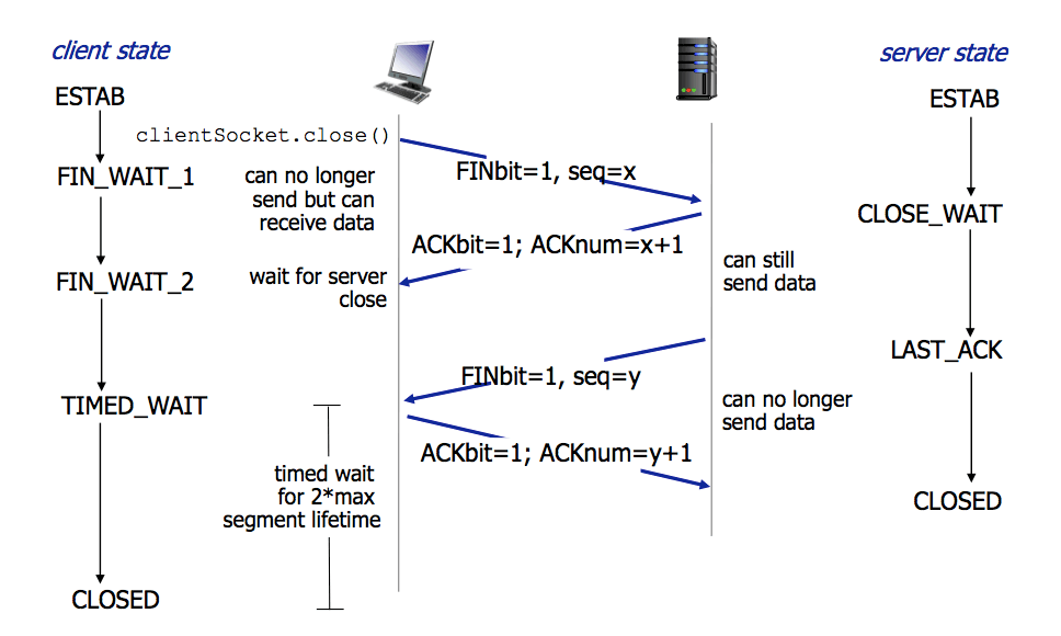
XVI. TCP Four-Way Handshake
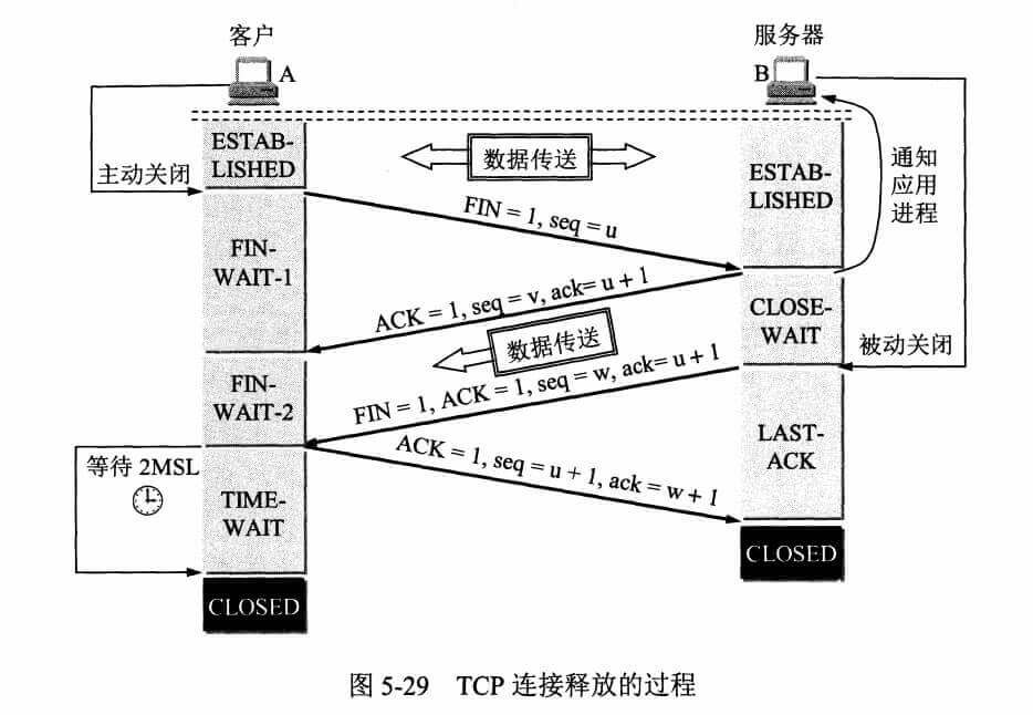
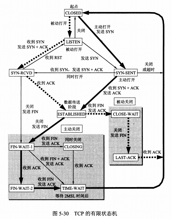
Tearing down a TCP connection requires sending four packets, so it is called a four-way handshake, also known as an improved three-way handshake. Either the client or the server can actively initiate the teardown. In socket programming, either side can trigger the handshake by calling close().
- First handshake (FIN=1, seq=x)
Assume the client wants to close the connection. The client sends a packet with the FIN flag set to 1, indicating that it has no more data to send, but can still receive data.
After sending it, the client enters the FIN_WAIT_1 state.
- Second handshake (ACK=1, ACKnum=x+1)
The server acknowledges the client’s FIN packet by sending an acknowledgment packet, indicating that it has received the client’s request to close the connection, but is not yet ready to close the connection.
After sending it, the server enters the CLOSE_WAIT state. After the client receives this acknowledgment packet, it enters the FIN_WAIT_2 state and waits for the server to close the connection.
- Third handshake (FIN=1, seq=y)
When the server is ready to close the connection, it sends a request to terminate the connection to the client, with FIN set to 1.
After sending it, the server enters the LAST_ACK state and waits for the final ACK from the client.
- Fourth handshake (ACK=1, ACKnum=y+1)
The client receives the close request from the server, sends an acknowledgment packet, and enters the TIME_WAIT state, waiting for any possible ACK packet that may require retransmission.
After the server receives this acknowledgment packet, it closes the connection and enters the CLOSED state.
After waiting for a fixed period of time (two maximum segment lifetimes, 2MSL, 2 Maximum Segment Lifetime), if the client does not receive an ACK from the server, it assumes that the server has closed the connection normally, so it also closes the connection and enters the CLOSED state.
The four-way handshake is illustrated below:
Why Does TCP Use a Four-Way Handshake? / Why Does Establishing a TCP Connection Require Three Steps, While Releasing a Connection Requires Four?
Because TCP is full-duplex. After the client requests to close the connection, the connection from the client to the server is closed (the first and second handshakes), while the server continues transmitting any remaining data to the client (data transfer). Then the connection from the server to the client is closed (the third and fourth handshakes). Therefore, when TCP releases a connection, the server’s ACK and FIN are sent separately (with data transfer in between), whereas when TCP establishes a connection, the server’s ACK and SYN are sent together (the second handshake). This is why establishing a TCP connection requires three steps, while releasing a connection requires four.
Why Can ACK and SYN Be Sent Together When Establishing a TCP Connection, While ACK and FIN Are Sent Separately When Releasing It? (ACK and FIN Being Separate Refers to the Second and Third Handshakes)
Because when the client requests to release the connection, the server may still have data to transmit to the client. Therefore, the server must first respond to the client’s FIN request (the server sends ACK), then transmit the data, and after the transmission is complete, the server sends its own FIN request (the server sends FIN). During connection establishment, there is no intermediate data transfer, so ACK and SYN can be sent together.
Why Does the Client Need to Wait for 2MSL in TIME-WAIT at the End of Connection Release?
- To ensure that the final ACK segment sent by the client can reach the server. If it does not arrive successfully, the server will retransmit the FIN+ACK segment after a timeout; the client then retransmits the ACK and restarts the timer.
- To prevent stale connection-request segments from appearing in this connection. Keeping TIME-WAIT for 2MSL ensures that all segments generated during the lifetime of this connection disappear from the network, so old connection segments will not appear in the next connection.
What happens if the ACK returned by the client in the TIME_WAIT state is lost? Because the server has not received the ACK number, it may send the FIN again. At this point, if the client does not wait for a period of time and instead closes the connection immediately, the corresponding port number used for the communication will also be released. If an application then happens to create a socket and is assigned the same port number, and the server’s FIN packet happens to arrive, that FIN—which was originally intended to close the previous connection—will start tearing down this newly established connection because the port number is the same. This is why the client needs to wait for a period of time: to prevent this kind of erroneous operation.
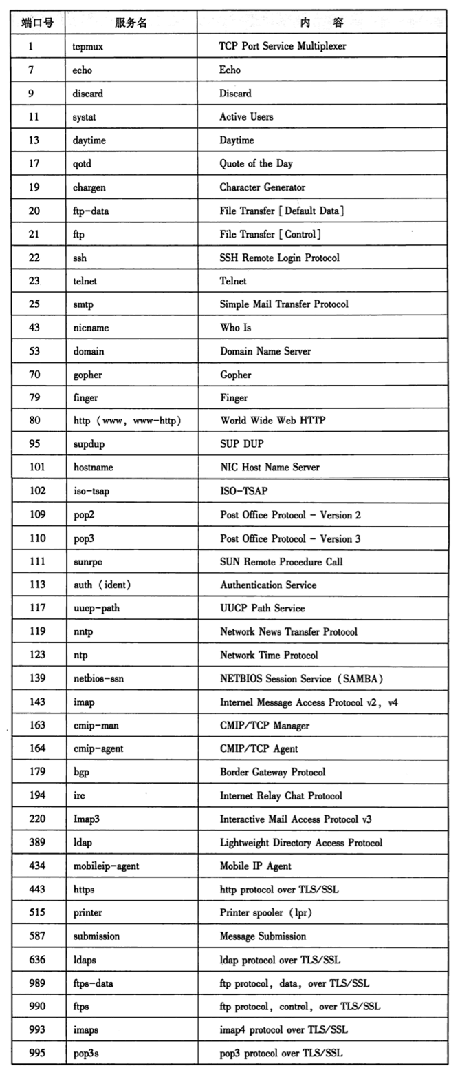
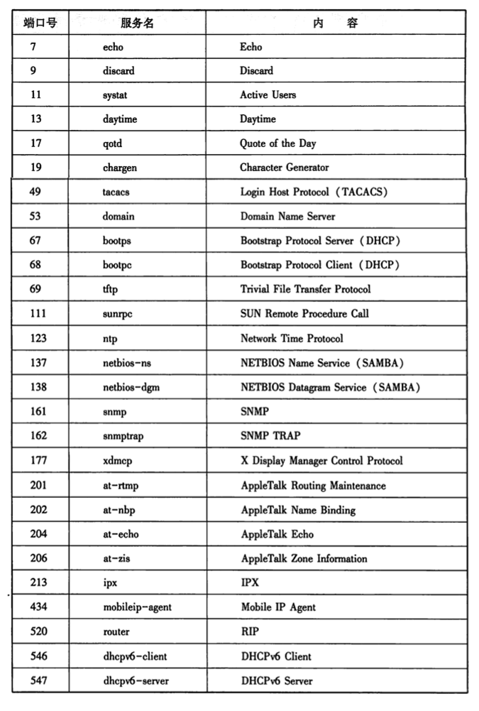
Common Ports
Well-known port numbers are generally assigned from the range 0 - 1023.
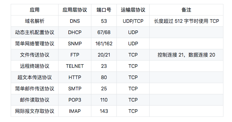
Well-known ports represented by TCP:
Well-known ports represented by UDP:
XVII. Socket Interfaces
From the perspective of the Linux kernel, a socket is an endpoint of communication. From the perspective of a Linux program, a socket is a file with a corresponding descriptor. Opening a regular file returns a file descriptor, while socket() is used to create a socket descriptor that uniquely identifies a socket. This socket descriptor is like a file descriptor: subsequent operations all use it as a parameter to perform operations through it.
Common functions include:
socket()
bind()
listen()
connect()
accept()
write()
read()
close()
Socket Interaction Flow
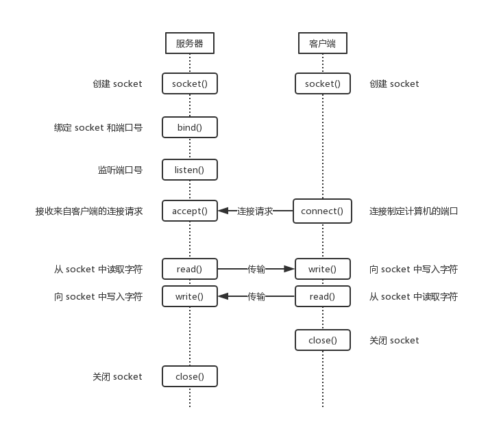
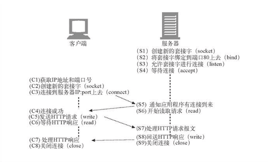
The figure shows the socket interaction flow for the TCP protocol, described as follows:
- The server creates a socket based on the address type, socket type, and protocol.
- The server binds an IP address and port number to the socket.
- The server socket listens for requests on the port number and is ready to receive connections from clients at any time. At this point, the server socket is not fully open.
- The client creates a socket.
- The client opens the socket and attempts to connect to the server socket using the server’s IP address and port number.
- The server socket receives the client socket request, opens passively, and begins receiving the client request until the client returns connection information. At this point, the socket enters a blocking state. The blocking occurs because the accept() method does not return until the client returns connection information; it then begins processing the next client’s connection request.
- The client connects successfully and sends connection status information to the server.
- The server’s accept() method returns, and the connection is established successfully.
- The server and client transfer data through network I/O functions.
- The client closes the socket.
- The server closes the socket.
In this process, the part where the server and client establish the connection reflects the principle of TCP’s three-way handshake.
Reference:
《Illustrated TCP/IP》
《TCP/IP Illustrated, Vol. 1: The Protocols》
《How Networks Connect》
GitHub Repo: Halfrost-Field
Follow: halfrost · GitHub
Source: https://halfrost.com/tcp_ip/